
Mobile:18928206361
Telephone:0769-82586018
Fax:0769-81668689
E-mail:sales@pxmotorsm.com
From an AC converter equipment developed in the middle of twentieth Century, in order to solve the difficulties of traditional AC motor speed control, speed control structure of complex equipment and efficiency and reliability are unsatisfactory and the disadvantages.
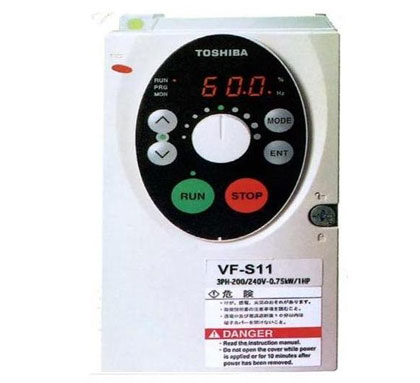
Frequency converter
VVVF is from an AC speed control equipment developed in the middle of twentieth Century, in order to solve the difficulties of traditional AC motor speed control, speed control structure of complex equipment and efficiency and reliability are unsatisfactory and the disadvantages;
As the frequency converter makes AC motor speed range and speed performance improved greatly, AC motor is gradually replacing DC motor in all kinds of application fields, including AC servo control field;
Inverter control objects: three-phase AC asynchronous motor and three-phase AC synchronous motor, the standard adaptive motor pole number is 2 / 4 / 8 poles;
Electric drive system composition of frequency converter
Inverter function characteristic
1) very good cost performance;
2) easy to operate;
3) mechanical characteristics of hard, small static rate;
4) the speed stability is good;
5) wide range of speed adjustment advantages.
Application field of frequency converter
Load characteristic of electric drive system
Working principle and control mode of frequency converter
The speed N formula of alternating current motor is:
N = 60F (1s / P)
Medium: f— frequency;
P— extreme logarithm;
S— slip rate (0 to 3% or 0 to 6%);
4.1. frequency control principle
Inverter: change the three-phase asynchronous motor power frequency, can change the synchronous speed, to achieve the purpose of speed regulation.
The rated frequency is called the fundamental frequency. When the frequency conversion speed regulation is applied, it can be raised from the basic frequency to the constant speed or from the fundamental frequency to the constant frequency. Therefore, the variable frequency speed regulation is much simpler than changing the pole log P and the slip s two parameters.
4.2. inverter control algorithm
The control core of AC speed regulation is that only when the motor flux is constant can the motor output be guaranteed, the ideal speed control effect can be obtained;
V / F control — — simple and practical performance in general, the most widely used, as long as the output voltage and frequency constant can approximately keep constant flux at low frequency, stator resistance voltage drop will cause magnetic flux decline, output voltage should be appropriate to improve;
Vector control — — excellent performance and can be comparable with the DC speed, mature late, imitate the control method of DC motor, using the vector coordinate transformation to realize the decoupling of the stator excitation current component and torque component of current control, constant motor flux, and achieve good performance of torque control, to achieve high performance control. Good performance, control the same complexity;
4.3. inverter technology development
PWM (PulseWidthModulation) modulation
&middot: PWM modulation is the use of semiconductor switching device on and off, the DC voltage into a variable voltage, frequency variable voltage pulse column.
· SPWM modulation is: using triangle and sine wave PWM waveform intersection direct control of each switch can get the pulse width and the pulse of the output pulse voltage ratio for variable sinusoidal variations, the control effect can get ideal output current is approximately sinusoidal.
&middot the carrier frequency must be high in order to ensure that the waveform obtained after modulation is the same as before modulation.
· GTR inverter because the switching frequency is too low, the motor noise is larger, IGBT effectively solve this problem.
Basic structure of 4.4. frequency converter
The basic circuit of a general frequency converter is shown in the figure above. It consists of four main parts:
1&mdash: rectifier part: change AC voltage into DC voltage; convert AC into DC power electronic device, its input voltage is sine wave, input current is non sinusoidal, and has harmonic;
2&mdash: filter part: the larger impulse DC filter, into a relatively smooth dc;
3— inverter: DC power and convert the three-phase alternating current, the inverter circuit is the use of power switch components according to the driver, the output pulse width control circuit by PWM wave modulation, or sinusoidal pulse width modulation SPWM wave, when the voltage is applied to the waveform of the load when the load due to inductance, the current continuous and become close to the sine wave current waveform;
4— the control circuit for generating output inverter to the driving signal, the signal is determined by external instructions, frequency of rise and fall, external control and fault protection through comprehensive control of inverter internal various signal and feedback etc.;